2015 — RACOMTECH PTY LTD

July 17, 2015 no comments


RFSim99 is a free linear S-parameter based circuit simulator offering schematic capture, simulation, 1 port and 2 port S-parameter display and file support, tolerance analysis, stability circles, and much more. Below is the sample for using RFsim99 to design a RF filter achieved the Combined 144MHz Low-Pass and 432 MHz Notch Filter

Design a Combined 144MHz Low-Pass and 432 MHz Notch Filter

Design Steps

1) Add the ports and components to the design screen shown on the picture -1. all components and ports are listed on the left side of deign screen, the first section is the rotating components, wiring connection, and ports, the second left section is the components of the resistor, capacitor , inductor and transmission line as well, the third section includes the models of the transformer, Op- amplifier, 1 port of S-parameters, and 2 ports S-parameters

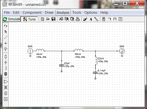
2) Click the "Simulate" on top left of the screen to start simulate the filter circuit, the simulation results will be plotted on the picture-2

Fig-2 Simulation results

Moving the mark on the bottom of the plot screen to find the -70dB of attenuation on notch frequency 433.5MHz. We can tune the notch frequency with the capacitor of 6.14pf on the simulation screen.

Fig-3 Simulation results

3) Use the components library to make the air cored inductor.

Double click the component of 40H inductor to show the edit screen Fig-3

Fig-3 Edit Inductor

Calculate the physical size and turns for the air cored inductor of 40H.

Fig-4 Inductance calculator

4) Build your filter

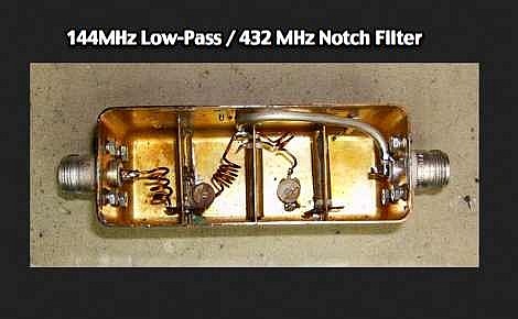
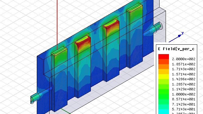
Reference: The picture of the sample is the combined 144MHz low pass and 432MHz notch filter, it was made by Bertrand Zauhar.


Download RFsim99

1) For Windows 95, 98, NT or 2000. File size 2045K

Download RFsim99-WinXp

2) For Windows 7/8: Download: RFsim99-Win7/ Win8RFsim99


3) Download the file, un-zipped with Winrar ( Download Winrar) , use the software directly.


4) Introducing a professional filter design website: RFCURRENT.com


There are many wireless antenna connectors. The type of wireless antenna connector you may need will depend on the Manufacturer and Type of device you have. Most people get confused of the gender of antenna connectors because many of them are Reverse Polarity (RP). A male reverse polarity connector such as RP-SMA male will not have the pin that many identify with. Below is a chart of some of the most common connectors. We carry a full line of wireless antenna connectors and wireless pig tails to meet your needs.

N

RP-SMA

RP-TNC

Female

n wireless antenna connector rp-sma wireless antenna connector rp-tnc wireless antenna connector

Male

n wireless antenna connector rp-sma wireless antenna connector rp-tnc wireless antenna connector

MC

MMCX

mc wireless antenna connector mmcx wireless antenna connector
mc wireless antenna connector

Introduction:

Array 366X series product, as the high-efficient programmable switching power supply, is characterized by low output
ripple and noise which rival traditional linear power supply. The dual lines LCD, full function keyboard and reliable
rotary knob make its operation quite convenient and speedy. Supporting the SCPI commands , equipped with optional RS232 and
GPIB interfaces, this series product is well suited for your design and test requirements.

Feature:

  • Provides CV and CC operating modes, switching automatically
  • The output voltage and output current are continuously adjustable from 0 to the maximum rating values
  • The maximum rating current can be achieved at 10mV. Equipped with SENSE terminals to compensate for the line loss
  • High power factor, high efficiency, wide line voltage range as well as low output ripple and noise
  • Multi-group setting parameters storage and recall
  • Robust, compact and convenient
  • SCPI (Standard Commands for Programmable Instruments) compatibility
  • Reliable input/output protections guarantee the effective operation in severe environment
  • The output voltage and output current are continuously adjustable from 0 to the maximum rating values

Specifications:

Model 3662A 3663A 3664A
Voltage 0 ~35V 0 ~80V 0 ~120V
Current 0 ~14.5A 0 ~6.5A 0 ~4.2A
Ripple and Noise (20 Hz to 20 MHz)
Voltage

<3mVrms
<10mVp-p

<5mVrms
<14mVp-p

<8mVrms
<18mVp-p
Current <2mArms 500uArms 500uArms


Download Data sheet - Download

Introduction:

3720A,3721A,3722A and 3723A Electronic Loads provide an adaptable, and functional asset wherever power sources need to be tested.These units are designed to provide high reliability, great performance, and ease of operation with multiple functionality.

Features:

  • 4 basic functions: CC, CV, CR, and CP ; and 8 basic test modes: CCL, CCH, CV, CRL, CRM, CRH, CPV, CPC
  • High-speed sequence, high-speed transient, short-circuit, battery discharge and other auxiliary functions
  • Minimum operating voltage is less than 0.6V at the load's full rated current
  • Optional zero-voltage test accessories are available
  • Programmable current slew rate
  • Perfect protection assures high reliability in the most complicated of test environments
  • Multiple groups of parameters and lists can be saved and recalled
  • Rugged structure, exquisite user-friendly design and convenient operation
  • Supports SCPI (Standard Commands for Programmable Instrumentation) and Labview, and provides necessary PC software
Detail Specifications can be found from the page of Eyou Electronics Australia - Link: ARRAY 3721A, 3720A, 3722A, 3723A